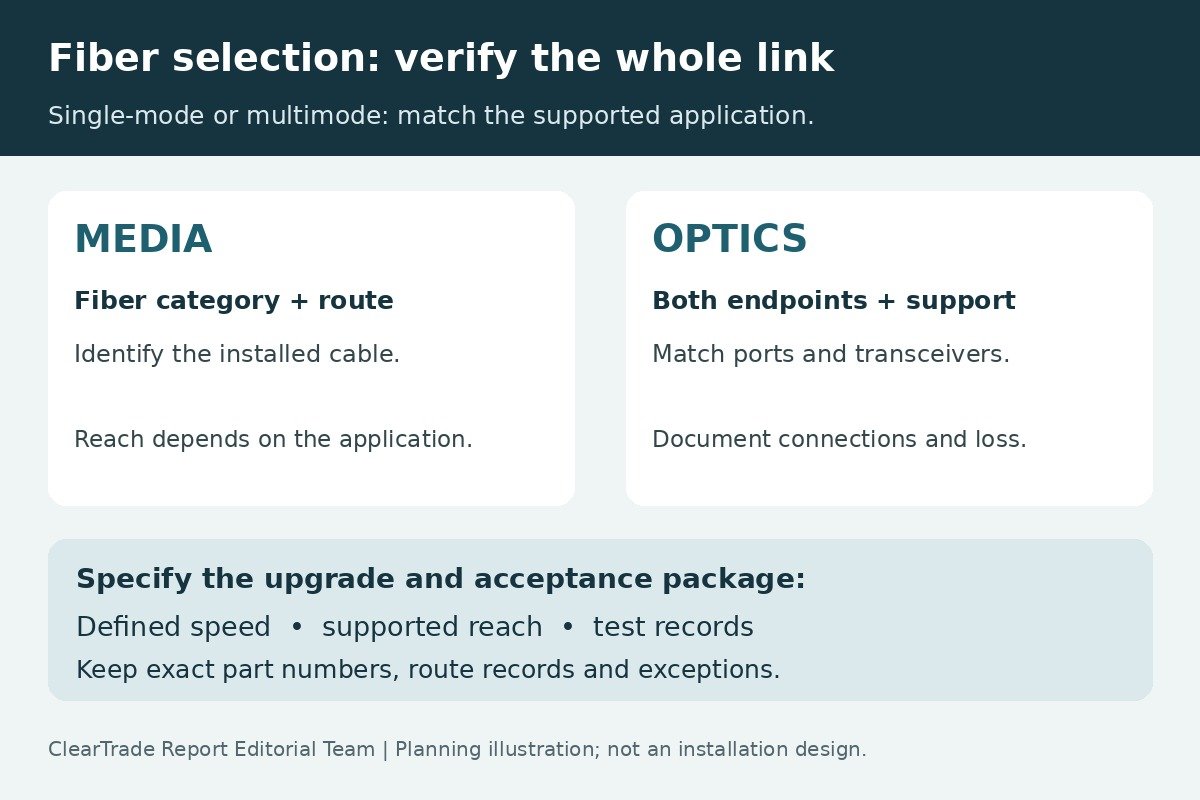
Choose a premises fiber system by matching the required application, installed route and supported optics—not by cable color or a blanket claim that one fiber is faster. Single-mode can support longer links with appropriate optics; multimode remains an option for supported shorter links. Neither label establishes that a particular switch-to-switch connection will work.
This comparison helps small-business owners and IT specifiers request a documented design and quotation. Manufacturer examples illustrate reach differences, not product recommendations or ClearTrade test results. Sources were checked October 27, 2026.
Start with the connection you need
Write down the two endpoints, present network speed, anticipated upgrade, actual cable route and the equipment at each end. Include patch panels and equipment cords in the proposed channel. A straight-line distance between rooms does not describe the installed route.
The Fiber Optic Association’s design guidance calls for analyzing link loss during design, before installation. Use that review to compare the whole proposed connection. Asking only for “fiber between the buildings” leaves the installer and equipment supplier to make assumptions about important interfaces.
For each endpoint, record the switch model, port type, operating software and intended transceiver part number. Obtain a written compatibility confirmation for that combination. A module physically fitting into a port does not, by itself, document support. Decide who owns that confirmation before cable installation and switch procurement become separate purchases.
What single-mode and multimode describe
Cisco’s physical-infrastructure guide, a February 2023 reference, distinguishes the media by core size and transceiver design. It identifies OM1 as legacy 62.5/125-micrometer multimode and OM2 through OM5 as 50/125-micrometer multimode. It also discusses OS1 and OS2 single-mode designations. These are media categories, not universal network-speed guarantees.
For an existing plant, ask for the original cable specification and test records. “Multimode” is incomplete when the planned application depends on the OM category. Likewise, do not infer a complete single-mode cable specification from a yellow jacket. Require the exact manufacturer part number and documented fiber category.
Avoid turning an older guide’s cost preference into a current universal buying rule. Obtain present quotations for the actual cable plant, optics, termination, testing and support. The right comparison is the total supported system at your route length and upgrade target.
A bounded 10-gigabit reach example
Cisco’s 10GBASE SFP+ data sheet, updated October 6, 2026, illustrates why exact pairings matter. Its SFP-10G-SR entries specify 850-nm multimode operation and list 300 meters on OM3 and 400 meters on OM4. Its SFP-10G-LR entries specify 1310-nm operation on G.652 single-mode fiber and list 10 kilometers.
Those are specifications for the listed modules and media under the data sheet’s conditions. They are not promises that every multimode link reaches 400 meters, every single-mode application reaches 10 kilometers, or an existing cable is acceptable because its route is shorter. Do not reuse these figures for a different speed or optical interface.
The same sheet directs readers to platform and software compatibility information. It specifies dual LC/PC connectors for the SR and LR examples and supports PC/UPC patch cords rather than APC. Verify the exact current module documentation when ordering; this article does not establish stock, lifecycle status, recall clearance or suitability for a specific switch.
Use a comparison sheet before requesting prices
Build one evidence sheet for the current application and another for the proposed upgrade. Missing information should remain explicitly unresolved rather than becoming an assumed pass.
| Decision | Evidence to request | Question the quotation must answer |
|---|---|---|
| Application and reach | Intended speed, measured route and exact optical interface | Is this complete channel supported at the required length? |
| Existing or new fiber | Manufacturer part number, fiber category and installed records | What evidence identifies the actual cable plant? |
| Endpoint compatibility | Switch, port, software and transceiver identifiers | Who confirms support at both endpoints? |
| Connections and loss | Patch cords, panels, splices and documented loss analysis | What allowance and acceptance criteria apply? |
| Growth and handover | Upgrade scenario, spare-fiber plan and test deliverables | What changes later, and what evidence will the owner receive? |
Keep the alternatives comparable. A quotation that includes optics and test reports should not be compared directly with a cable-only price. Identify exclusions, allowances and unresolved assumptions beside each total.
Reach and loss are separate checks
FOA’s loss-budget reference distinguishes the estimated loss of the cable plant from the loss a data link can tolerate. Connections, splices and fiber contribute to the plant calculation. The equipment’s operating constraints still matter; a low-loss result does not erase bandwidth or dispersion limits. Some links also have minimum-loss constraints associated with receiver overload.
Ask for a calculation covering the actual channel at the applicable wavelength and an explanation of the chosen component values and margin. Include the interfaces that will remain in service. Do not accept an unexplained number copied from a generic diagram as proof that your link is designed.
This guide deliberately does not supply a universal connector-loss allowance or pass/fail threshold. The designer should identify the applicable system limits, test method and project requirements. Preserve that basis so a later repair or added patch panel can be evaluated against the original assumptions.
Connector shape is only one part of compatibility
The connector family, fiber type, polish and channel arrangement all belong in the record. Fluke Networks explains that UPC and APC have different endface geometry and cannot be mated; attempting it can damage the endface. A connector looking similar is not sufficient evidence of compatibility.
Ask the supplier to identify both ends of each patch cord and every mating interface. Where an upgrade changes interfaces or fiber use, have the revised arrangement documented rather than assuming that the original patching remains valid. Do not improvise adapters or treat a color convention as a substitute for part-number verification.
Have a qualified installer handle inspection, cleaning, termination and testing with appropriate equipment and procedures. This is a procurement and scope guide, not a laser-inspection or fiber-handling procedure. ClearTrade has not inspected the proposed equipment or tested the reader’s plant.
Plan upgrades as a specific scenario
Replace “future-proof” in a proposal with a defined question: what speed and interface are being reserved for, over what channel, and which components would change? Ask separately about cable reuse, optics replacement, patching changes and the need for additional fibers.
For example, an owner may request prices for the present connection and a documented later upgrade using the same route. The supplier should identify which assumptions are supported now and which depend on future equipment selection. An unidentified future transceiver cannot provide present proof of compatibility.
Consider spare capacity and route diversity as separate choices. Extra fibers in one cable do not, by themselves, establish a physically independent path. Put the intended operational benefit in the scope so the owner can assess the proposed provision instead of buying a strand count without context.
The cable’s optical category also does not settle its installation environment. Ask the installer to address pathway conditions, applicable cable ratings, manufacturer installation limits and any building-entry or enclosure requirements separately. This article does not determine local code compliance or specify a cable construction for a particular route.
Define the acceptance package
FOA’s testing overview distinguishes insertion-loss testing from the diagnostic information an optical time-domain reflectometer can provide. An OTDR can help locate faults and assess events when properly used, but a report must be interpreted in the context of its method and setup. “Tested” without the test basis is incomplete.
Before work starts, agree on the required records:
- Endpoint and cable identifiers linked to a route drawing and fiber schedule.
- Exact media, connector, patch-cord and transceiver part numbers.
- The design loss calculation and agreed application-specific acceptance criteria.
- Test results identified by fiber, wavelength, direction and method as required by the project.
- The actual installed configuration, exceptions, repair records and responsible support contacts.
Require exceptions to be resolved or clearly documented. A link establishing traffic today is useful operational evidence, but it is not a substitute for the contracted acceptance records or proof of an unspecified future upgrade.
If the decision also involves copper access cabling, see our Cat6 versus Cat6A guide. It covers a different media decision. For preserving the final system records, see the building handover checklist.
When reviewing the delivered test files, use our fiber loss-budget acceptance guide to reconcile the installed path, calculated allowance, reference method and measured result. Keep application limits and unresolved exceptions visible alongside the pass/fail summary.
For the broader pathway and media decision, compare fiber, copper and wireless links between buildings, including electrical exposure, remote power and acceptance records.
Frequently asked questions
Is single-mode always the better choice?
No universal answer follows from the fiber label. Compare the supported application, route, optics, installed cost and defined upgrade scenario. Require evidence for the complete channel at both endpoints.
Can I assume all multimode fiber supports the same distance?
No. Fiber category and optical interface matter. The cited Cisco SR example lists different reaches for OM3 and OM4; those figures do not establish limits for every speed or module.
Does a passing loss test prove a future speed upgrade will work?
No. A loss result addresses the documented test and limits. A later application also needs compatible media, optics, endpoints and reach under its own requirements.
Can APC and UPC connectors be mated if they fit?
No. Their endface geometries differ, and mating them can cause damage. Confirm the specified connector and polish at each interface rather than relying on appearance alone.
Sources and scope
Primary references checked October 27, 2026: FOA network design, loss-budget and testing guidance; Cisco physical-infrastructure reference dated February 2023; Cisco 10GBASE SFP+ data sheet updated October 6, 2026; Fluke Networks APC/UPC explanation dated October 11, 2018. Relevant sections link directly to these references. Historical guidance is context, not a claim that ClearTrade reviewed a current paid standard.
No products are ranked or recommended here. No hands-on testing, outside professional review, named-site design, installation acceptance or warranty entitlement is claimed. The original ClearTrade Report Editorial Team graphic is a conceptual evidence checklist, not a network design or product photograph.
AI tools assisted with drafting. ClearTrade Report Editorial Team checked the cited sources and edited this guide. No hands-on inspection or testing was performed.
Need a qualified professional?
Trusted Pros uses visible license-verification states and never ranks paid listings above unpaid listings.